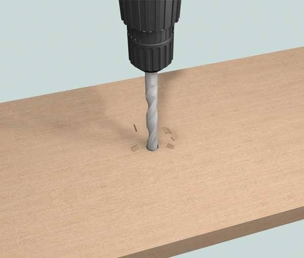
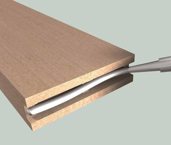
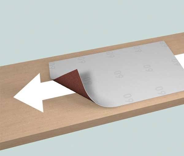
Salamander outdoor profiles do not differ from wood in look and feel, nor in processing. Thus, they can be sawn, milled, drilled, glued, sanded, glazed, painted and bent like wood.
Best of all, unlike wood, Salamander outdoor profiles do not crack, swell or splinter.
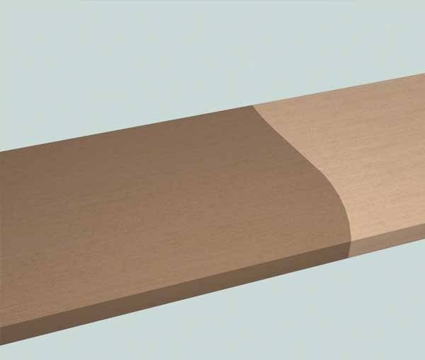
NOTE: In the case of glazing/painting, the respective color tone of the profile is naturally highly dependent on the base material, sanding pattern and paint application quantity. Therefore, no liability can be accepted for color variations or differences between the profiles supplied.
In order to achieve a uniform appearance of the installed profiles, it is recommended, especially in the facade area, to process profiles from several packages at the same time, i.e. to cross-mix them from at least five to six packages/pallets. Only in this way are the profiles optimally mixed and the natural play of colors is shown in its uniform beauty.
As your reliable system partner, we want to give you access to the most important documents you need for your project planning around the clock and independently of our office hours. For this reason, a comprehensive portfolio of technical data as well as information and marketing material is available for download in our service area.
How to install your Resysta decking boards from Salamander
In order to install Salamander brand Resysta decking in your garden, you should consider the following points in advance:
Profile storage To avoid damage, only store the profiles horizontally on level surfaces. The distance between the supports should not exceed 400mm.
Substrate The substrate must be level, load-bearing and frost-proof. Make sure that rainwater can run off and seep away unhindered.
Rear ventilation To ensure rear ventilation of the profiles, the spaces between the substructure profiles must not be filled. Make sure to keep a minimum distance of 10mm to fixed parts of the building or other fixed points.
Profile length The profiles are always produced with excess length. Precise, needs-based cutting is carried out on both sides during installation on the construction site.
Gradient Basically, no slope is required for the installation of Salamander Resysta decking boards. Standing water or freezing water in the hollow chambers does not cause damage. Nevertheless, we recommend a slope of 1-2 percent. On the one hand, a slope ensures that water runs off the surface - this has a more visually appealing effect - and on the other hand, it ensures that possible impurities are washed off the terrace - the so-called self-cleaning effect.
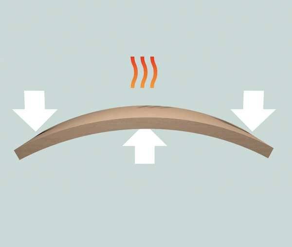
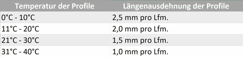
Linear expansion The profiles expand when the temperature increases. Therefore, the linear expansion of the profiles must be taken into account during assembly.
Example: At a material temperature of 15°C and a profile length of 3000 mm, a distance of 6 mm is required during installation.
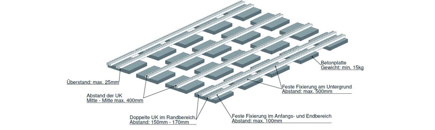
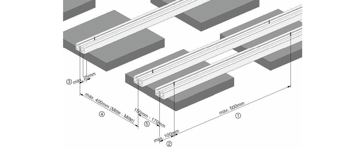
The assembly of the substructure systems
Fix the substructure profiles firmly to the substrate at a maximum distance of 500 mm. A strip foundation or concrete slabs are suitable here, for example.
The fastening distance at the beginning and at the end must not exceed 100 mm.
The distance between the substructure must not exceed 25 mm.
The distance between the substructure profiles must not exceed 400 mm (from center to center).
Install an additional substructure profile in the edge area and at profile joints at a distance of 150 - 170 mm.
Use two substructure profiles at the profile joint.
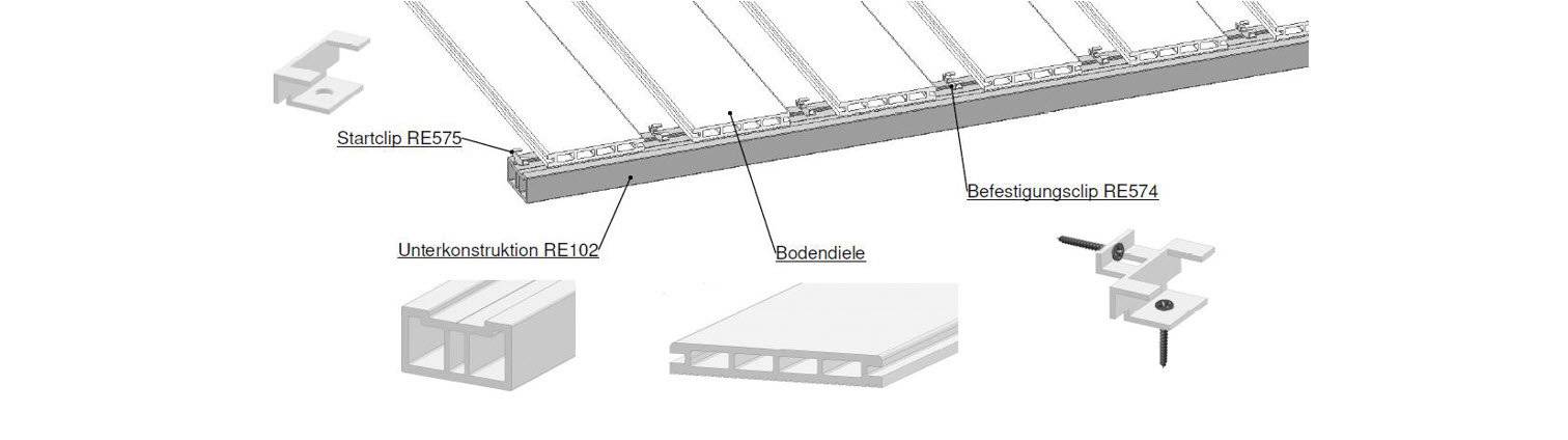
The assembly of the substructure profiles
Screw the start clip to the substructure. If the distance between the screw and the start of the substructure is less than 15 mm, pre-drill with a diameter of 2 mm.
Slide the floor board under the tabs of the start clips.
Make sure that the projection of the profiles to the substructure is a maximum of 25 mm.
Now insert the RE574 fastening clip and screw it to the substructure.
Mount a clip with a screw on the substructure at each cross point between the substructure and the floor board.
Now screw a screw through the lug in the RE574 fastening clip into the groove cheek of the floor plank. This determines the direction of the expansion. ATTENTION: The groove cheek is only fastened at one point per profile.
The assembly of the last floor board is done by a visible screw connection. For a more precise positioning of the screws, we recommend pre-drilling with a diameter of 2 mm and slightly countersinking so that the screw head is flush with the profile surface.
Like the last floor board, the wall strips are also visibly screwed at a distance of 400 mm.